Page 1 of 5
taking the IQ radio apart and soldering the 20 pin connector
Posted: Sun Apr 10, 2016 1:52 pm
by mercialogo
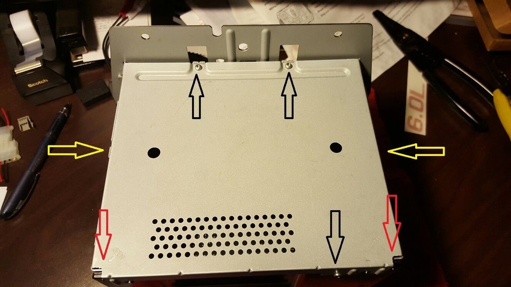
Once you have the radio out, you will find 3 screws, 2 on the top toward the front and 1 on the back to take the top plate off ( Black Arrows ). You will also see and 2 pry points ( Red Arrows ) to remove the top plate. There are also 2 screws on 1 on each side that you will need to remove so that the module board that the 20 pin connector will need to be soldered onto.
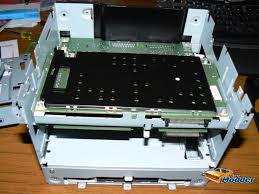
Once the top plate is off and the 2 side screws are out, you can pry the module out ( pry right where you removed the screws ). Here is a pick of the module
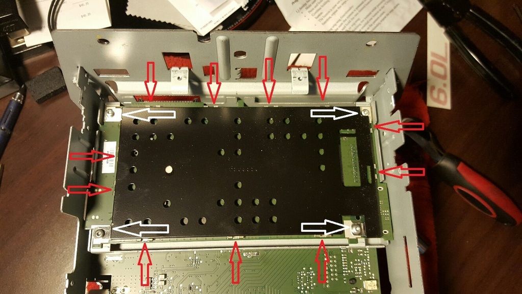
The module itself has 4 screws ( white arrows) that hold on a black plate. There are a few clips (Red Arrows )that hold on the black plate. Just softly pry up on the black plate and it will pull up from those clips.
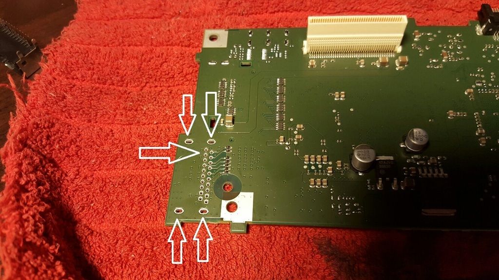
Once the black plate is off you now have access to where you install and solder the connector in. I forgot to take a picture of the connector but you can see where it goes onto the board. You have 4 main holes that hold the connector to the board and the 20 pins. I have marked the 4 pins that are needed for the 2 video feeds. I only soldered these 8 places as that's all that is needed.
Re: taking the IQ radio apart and soldering the 20 pin conne
Posted: Sun Apr 10, 2016 5:10 pm
by smwalker
Wow lots of room in there. Wonder if we could fit in some kind of audio processor in there to turn the (2013) 2 channel stripped down box into a 5 channel system for use with external amps. The 13's would be bumping!!
Re: taking the IQ radio apart and soldering the 20 pin conne
Posted: Tue Apr 12, 2016 5:43 pm
by ejf2461
Smwalker, Thanks so much for taking the time to take pics of this. LRF Electronics in Greenfield, IN 317.462.2272 has my radio and is going give me/you guys a price for soldering on RCA's for rear video or the 20 pin connector and adding rear speaker finals for so we can actually hear these radios. A few things they have found on my radio is how low the power output is. Less than 3 watts! A few questions I am waiting to have answered is if multiple channel RCA's...including hi volt can be added for adding 4,5 or even 6 channel amplifiers. Smwalker since you were asking about the center channel I had the dealer confirm at least on my Caprice that the speaker is not installed from the factory and neither is the wiring. Maybe if they can add 2 rear speaker finals then its possible to have a center channel final added also. These guys seem very knowledged on electronics & circuit boards so there may be hope after all. I should know something very soon and will give you prices and updates.
Re: taking the IQ radio apart and soldering the 20 pin conne
Posted: Tue Apr 12, 2016 10:19 pm
by elc32955
Thanks very much for the research on this issue everyone! Sounds like it may be possible to upgrade these units after all then. EJF, when you're speaking with the vendor, you might also see if they have the capability to replace broken Fakra connectors on the motherboard for the AM/FM antenna if the silver boxes are benched. A lot of these radios are running around with no AM/FM simply due to the fact that someone broke the plastics of the connector off trying to remove the antenna connector in an improper manner. It'd sure be nice to establish a relationship with a rework facility, better then purchasing a whole new unit!
Just a suggestion since they're already diving into the unit

Thanks
Eric
Re: taking the IQ radio apart and soldering the 20 pin conne
Posted: Thu Jul 21, 2016 1:55 pm
by 91C02920
I just had RCA connectors soldered to my board.
Local TV repair shop did it for me. They are short, I went by to ask if they could do it, then went out to get a cable to use but when I came he had found cables and put it together already.

Clearly I already had the 20 pin connector on my board, but I can't find the cable in for under $100+shipping.
The tech soldered the negative to the shielding on the connector, and the positive to the pins on the back side of the connector.
Lets hope it works!

I had reached out to a Holden dealer asking about factory service plug 13586832 , and he said they are out of stock, none in Australia, though he didn't think they were discontinued yet.

Re: taking the IQ radio apart and soldering the 20 pin conne
Posted: Thu Jul 21, 2016 5:39 pm
by smwalker
Think the silver box is going to be able to slide into the dash OK with the connectors sticking out? Or are you going to have to modify the case support?
Re: taking the IQ radio apart and soldering the 20 pin conne
Posted: Thu Jul 21, 2016 7:17 pm
by ejf2461
Can you solder the RCA directly to the board without the 20 pin connector? If not where to you find the 20 pin connector?
Re: taking the IQ radio apart and soldering the 20 pin conne
Posted: Thu Jul 21, 2016 10:12 pm
by smwalker
As far as we can tell the connector has been discontinued so all that is left is whats in stock by a couple of vendors in AU and they have upped the part's price or will only sell it if you buy a complete radio system from them.
The connector part number from the manufacturer is CSC1020-1882F and the manufacturer was SMK. IF you run across any by em up!
Re: taking the IQ radio apart and soldering the 20 pin conne
Posted: Fri Jul 22, 2016 2:08 am
by 91C02920
smwalker wrote:Think the silver box is going to be able to slide into the dash OK with the connectors sticking out? Or are you going to have to modify the case support?
Not sure, this is a spare radio, I haven't pulled the one in my car out yet so I'll see.
But just trying to put the board together and those cables are too damn short, so I'll get them redone.
I think the way to go might be thinner gauge wire for sure, and no connector on the end so it could slide in with no issue, then even try the solder-less rca ends so it would be easy to take out again if you needed.
The right guy could take the connector out and put them right to the board, but that guy isn't near me lol.

The socket is CSS5020-1005F .
The whole connector line seems to be discontinued (didn't search for the socket), even though it is in the 2016 book-
http://www.smk.co.jp/p_file/CarEle2016c.pdf" onclick="window.open(this.href);return false; . I couldn't find anyone with any of the connectors, 18__F, 19__F, or 21__f, except for some sellers in China saying they have CSC1020-1961BLACK that I don't trust enough to send any money to.
Re: taking the IQ radio apart and soldering the 20 pin conne
Posted: Fri Jul 22, 2016 11:01 am
by smwalker
They put those boxes in there to obscure the part number for some reason. I somehow figured it was 82 that was hiding, but not sure it's the same for the right angle ones.